Use steam more scientifically
The steam chain is composed of 4 basic elements;
Steam generation (boiler, waste heat boiler or flash tank)
Steam distribution (transmission, steam turbine and steam pressure reduction system)
Use of steam (stripping, process heating, turbine drive, burner atomization, heat tracing, torch, HVAC-heating ventilation and air conditioning, etc.)
Condensate recovery (recover the heat energy in condensed water and desalinated water; reduce environmental impact and water treatment costs)
In factories using contemporary mainstream technology, more opportunities for energy efficiency improvement can be tapped through condensate recycling. This field is also the focus of many energy saving and emission reduction articles.
To maximize the utilization of steam, it is necessary to ensure the dryness (such as process steam) or superheat (such as steam turbine) of the steam. This requires the public sector to supply high-quality steam as much as possible, and in the transportation process Try to avoid losses. Since steam will produce condensate once it releases heat, it is necessary to strategically set a drainage point after the steam transmission pipeline and steam-using equipment. Once the condensate is formed, it can be removed through the drainage point.
In addition, the method of spraying high-temperature condensed water into the system is usually used to desuperheat the superheated steam. Therefore, the steam downstream of the desuperheating station may be too humid. In either case, as long as the condensate remains in the steam, it will have a serious negative impact on the steam system.
If the steam supply or condensate at the process side cannot be eliminated in time, the following consequences may be brought:
Production reduction-the heat carried by the condensate entrained in the steam into the process is much less than the steam
Nozzle damage-the entrained condensate can easily erode the nozzle and affect the vacuum or atomization
Power loss-entrained condensate will reduce the efficiency of the steam turbine
Increase maintenance load-water hammer can damage equipment, such as turbine blades, control valve packing, etc.
Increased safety risks-water hammer may threaten personal safety
Reduce process controllability-heat exchanger overflow will lead to unstable control
In many factories, the operators have realized the importance of removing the condensate in time once it forms, and implement it. Unfortunately, there is no proper condensate drainage or distribution system on site. Therefore, in many cases, the condensate will be directly discharged. Drain to the sewer or drain. This simple and direct operation is not an effective condensate treatment method, and is accompanied by the following hidden dangers:
Economic loss caused by waste of high temperature soft water
The steam turbine or other process equipment deliberately opens the bypass in order to prevent water accumulation or damage, resulting in a lot of waste of steam
Because of the increase in boiler feed water treatment capacity, the hidden danger of system corrosion is exacerbated
Condensate drainage is traditionally achieved by steam traps or equipment equipped with liquid level tanks and outlet controls. In some working conditions, the high back pressure of the condensate recovery pipeline downstream of the equipment may cause the phenomenon of "stagnation". At this time, a design combining a pump and a trap is required to discharge the condensate. It can be drained through the CRANC trap under a pressure difference, or it can be drained under a negative pressure by a pump, and it can also block steam at the same time, which is the so-called "pump drain" or "power drain".
At present, there are at least three condensate discharge modes to choose from, and the basis for the selection should focus on the "drain point" rather than the equipment that simply removes the condensate-"CRANC trap"; along this line of thinking, it will not happen. The conditions for installing other condensate drainage schemes only installed traps.
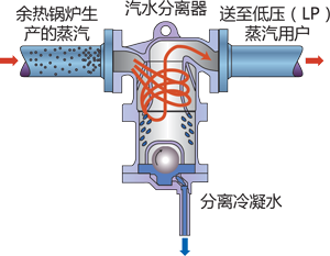
Figure 1 Improving the quality of steam produced by waste heat boilers
As shown in Figure 1, the CRANC steam-water separator is used to separate the condensed water entrained in the steam (including flash steam or regenerated steam) in the steam supply pipeline to deliver high-quality steam to the plant; on the other hand, The trap drains the condensate separated from the steam. "CRANC trap"-as the name implies, its role is to remove condensate and "block" steam. CRANC traps can not meet the high pressure or super large displacement conditions, the liquid level tank drainage scheme can be used.
In a factory, where condensed water is effectively removed and special design is required, more than one solution can be applied, as shown in Figures 2a and 2b, that is, the jacket pipe that transports high melting point materials such as liquid sulfur or high boiling hydrocarbons is hydrophobic. Two options.
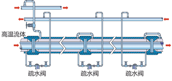
Figure 2a The best configuration of the drainage point of the jacket pipe for conveying high temperature fluid (such as sulfur)
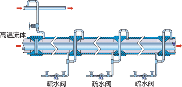
Figure 2b Another type of drainage point configuration (without "stagnation") for jacketed pipes for conveying high temperature fluids (such as sulfur) that is common in actual working conditions
For some special working conditions, such as steam-heated heat exchanger drainage system, first confirm whether the system may have "stagnation"; if it is, the condensate cannot be discharged through a simple steam trap. Generally, for systems with steam pressure control, if a negative pressure difference is formed before and after the drainage equipment, "stagnation" will occur; in this case, the so-called "Type II" secondary pressure drainage equipment-trap pump Figure 3), to ensure the drainage under the negative pressure difference of the system; and the so-called "Type I" secondary pressure drainage equipment-trap pump (Figure 4), is suitable for recovering and pumping condensate to a high back pressure recovery pipe, namely , The drainage equipment is always at a negative pressure difference before and after.
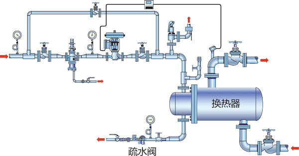
Figure 3 The configuration of the steam heat exchanger when there is always a positive pressure difference before and after the drainage equipment

Figure 4 The steam heat exchanger discharges the condensed water at the time of negative pressure difference between the front and rear of the drainage device (“stagnation”) through the “dynamic drain” method
Stop purging for no reason
In some factories, some operators have developed the habit of opening the purge valve at will, resulting in smoke around the equipment, even impassable, and various unknown sources of steam are discharged into the atmosphere. The operator may open the purge valve to protect the equipment, prevent overheating or increase production, product consistency, or to improve the fluidity of the fluid in the pipeline; so to speak, every time you see an open purge valve or steam on site Blowing is an intuitive manifestation of unreasonable setting of hydrophobic points, which is also inextricably related to poor process operation. The more common occasions where the purge valve is opened or the steam is leaked are heat exchangers (especially when stagnation occurs), heat tracing pipelines or jacketed tubes for high-temperature materials, and steam turbine steam supply pipelines.
The invisible steam leakage of the process heat exchanger system is more dangerous. For example, to ensure the normal operation of the process, the bypass may not be found immediately on site, but it does happen all the time. It seems that the process production It is normal, but the steam consumed is far greater than the actual need. Only after the improvement plan is implemented can the similar blow-and-leak phenomenon be prevented.
Looking at the purge pipeline at the inlet of the steam turbine, the staff are often worried that water hammer will damage the turbine blades. They feel that only by opening the purge valve at the inlet can potential water hammer damage be avoided; and for heating pipes or jacketed tubes, they often It will be found that the unreasonable installation in the initial stage to reduce the cost will end up paying a heavy price due to the frequent accumulation of water in the jacket. In desperation, the operator can only open the purge valve to ensure the normal flow of materials.
If you need to find countermeasures for all the above cases of steam leakage, you should investigate the reasons why you need to purge steam in the first place, find a more reasonable and complete drainage plan, and maintain or even improve the system while reducing steam consumption Performance, after all, leaking steam is quite wasteful.
By the way, the air system of many factories also incurs many undesirable consequences due to excessive blowing-the reason is very similar to that of the steam system. In many cases, the drainage equipment is blocked by impurities in the system and stops working. The improved air system drainage design will receive significant gains (Figure 5).
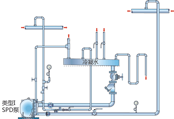
Figure 5 Recycling and transporting precious condensate back to the boiler systemSteam trap management
How long can steam traps last? Some people say that their factory's trap failure rate is 4%. For a mature factory, this means that the average life span of the trap is 25 years! Do you really hope that all traps in a chemical plant can reach an average life span of 25 years after undergoing various environmental tests? Behind this statement, there needs to be a test method that can quantify the service life of the traps; one method is to count the total number of traps replaced in the entire plant in the past 12 consecutive months, and add this value to the previous test. For the variables of the faulty trap, all the values are revised to the annual unit; on this basis, the number of faulty traps that need to be replaced in the following year is the estimated value of the annual failure rate.
For a factory that has not actively adopted annual trap inspection and maintenance, it is not surprising that the failure rate exceeds 50% (or higher); if this ratio is simply divided into two types: fault open and fault closed, it is conceivable that 25% of the steam traps in the entire plant are leaking steam; even if the annual steam leakage of each leaking trap is calculated at $1,500, multiplying by the total amount of traps in the entire plant and then multiplying by 25%, it is easy to estimate the annual loss. It is difficult to decide whether to correct it immediately. At least one trap manufacturer provides software that can clearly estimate the leakage of a faulty trap. The data provided by the software helps the factory determine the response speed of maintenance in the form of return on investment. Table 1 shows the basic statistical data of a factory trap detection system.
| Classification | Quantity | Proportion | Money loss | |
|---|---|---|---|---|
| Malfunction | Blow | 124 | 5.0% | $243,025 |
| leakage | 307 | 12.5% | $211,700 | |
| Blockage | 179 | 7.3% | $0 | |
| Low temperature | 294 | 12.0% | $0 | |
| total | 904 | 36.8% | $454,725 | |
| good | 1180 | 48.1% | $0 | |
| not sure | 371 | 15.1% | $0 | |
| total | 2455 | 100.0% | $454,725 | |
According to the expected use of the trap, determine whether to mark it with "scrapped" or "not put into operation". If it is found that the steam is running and the trap is closed, it may be that the trap was found to have leaked before and the on-site personnel closed the relevant valve (if the trap is blocked, it is usually not necessary to isolate it); if it is found that the steam is out of service (It may be that the steam used for plant shutdown or anti-freezing is not needed temporarily), at this time the state of the trap is unknown. For traps whose status is unknown, the failure rate of traps under similar operating conditions is usually used as a reference and a value is assumed.
Detection analysis helps determine maintenance response time. Once the routine testing procedures are established, the factory management can set the critical value according to the trap leakage level, determine the replacement priority, and also have a rough estimate of the return on investment of replacing the clogged trap (Table 2); then, the factory will The corresponding maintenance plan can be formulated according to the classification of the trap detection results. Based on this, the structure in Table 3 briefly explains how to provide a corresponding maintenance plan for each trap position through the "if/then" mode, and the specific instructions are as follows: "If the leaked trap" "$ loss" exceeds the critical value Value, then it should be replaced immediately; otherwise, continue to use. "
| Annual cost of replacing blocked trap | |
|---|---|
| $1,500 | |
| The cost of replacing a leaking trap | |
| pressure | Annual fee |
| 650 psig | ≥ $1,600 |
| 250 psig | ≥ $800 |
| 150 psig | ≥ $800 |
| < 50 psig | ≥ $600 |
| Trap | Application occasion | pressure (psig) | Test results | #/hr | $loss | Suggest next steps |
|---|---|---|---|---|---|---|
| Trap 1 | Supervisor drainage | 650 | Small leak | 23.20 | $1,837 | replace |
| Trap 2 | Supervisor drainage | 650 | Blow | 133.92 | $10,605 | replace |
| Trap 3 | Supervisor drainage | 250 | Blow | 77.12 | $4,810 | replace |
| Trap 4 | Supervisor drainage | 250 | Big leak | 50.46 | $3,147 | replace |
| Trap 5 | Heat Tracing | 250 | Leak | 21.21 | $1,323 | replace |
| Trap 6 | Supervisor drainage | 150 | Small leak | 14.13 | $962 | replace |
| Trap 7 | Heat Tracing | 50 | Not in operation | 0 | $0 | - |
| Trap 8 | Supervisor drainage | 50 | Blockage | 0 | $0 | replace |
| Trap 9 | Supervisor drainage | 50 | Big leak | 25.66 | $1,011 | replace |
| Trap 10 | Heat Tracing | 50 | Leak | 18.98 | $748 | replace |
| Trap 11 | Heat Tracing | 50 | Small leak | 6.11 | $241 | - |
| Trap 12 | Supervisor drainage | 25 | Blockage | 0 | $0 | replace |
| Leak valve | 370.79 | $24,684 | ||||
| Blocked valve | $3,000 | |||||
| total | $27,684 | |||||
People usually pay great attention to the replacement of leaking traps. The reason is very simple. Just like a fruit hanging on a low branch, you can quickly get a high return; however, by evaluating the reliability records of the entire plant's trap use, you can get extra Income. In some factories, the historical records of maintenance and inspections are clear and accurate. It can be found that after the inspection is completed each year, the failure rate information of the traps is clear at a glance; the total number of failures found in several inspections (including those that have been repaired and those that have just been repaired) When the total amount of traps in the entire plant has been accumulated to the total amount of traps that have not been repaired after inspection, it is equivalent to a "exchange" of the traps of the entire plant, similar to the completion of an "inventory turnover". This method can be used to measure the service life of traps. Through this analysis, factories can gradually use traps with more reliable performance and longer life.
Don't ignore low temperature traps
As mentioned in the previous article, based on the consideration of high return and high profit, usually factories will give priority to replacing leaky traps, while ignoring low-temperature and clogged traps. However, these low-temperature traps are often the cause of sudden catastrophic accidents. Precursor. There have been many lessons learned, because the low-temperature traps-and the low-temperature condensate drain points-caused the shutdown of the steam turbine at key locations or the failure of the main compressor, which caused the plant to shut down for several days; please remember that the designer of the system The original intention of designing the drain point—discharging with CRANC trap valve—is to maintain the normal operation and safety of the system.
In short, all cryogenic traps should be repaired or replaced in time. If there is no need to install a trap under certain circumstances, the trap should be permanently cancelled through the normal management change (MOC) procedure. Important note: When the MOC procedure is carried out, all possible consequences of canceling the drainage point should be fully considered, and the decision to cancel the drainage point should be absolutely safe.
The times are advancing, and technology is also advancing. The factory must develop more effective methods to manage the traps. The current best practice is to review or rectify the use of the entire plant's traps once or several times a year (if necessary). Configure the most effective drainage device for each condensate drainage point. At least one steam trap manufacturer can provide such an annual inspection service, and based on "best practices" to provide customers with the best solutions that keep pace with the times; in addition, professional engineering consulting can provide more variety for improving condensate drainage solutions Of the options.

Figure 6 Specially designed trap for high-pressure superheated steam pipeline
Balance and review
In today’s factories, good condensate recovery and management is indeed the most strategically promising way to improve the efficiency of the steam system. Even in many cases, regular inspections of the use of related equipment in the entire steam pipe network will unexpectedly find improvements. opportunity. It is worth mentioning that the purpose of steam balancing is not only to track the usage of the steam flow itself, but also to help find new load imbalance conditions for rebalancing and reduce low-pressure steam evacuation.
For example, the primary goal of steam balance is to find available places for evacuation/exhaust gas, one of which can be to preheat certain fluids around; another example is to combine the technology of trap pumps to replace the original medium pressure steam with low pressure steam For heat exchangers, the "power drain" mode of this trap pump can prevent condensate from accumulating in the heat exchanger under low pressure conditions, increasing output and equipment stability.
In certain applications of steam balance, the classification of primary and secondary (highest and second-highest) steam pressures can be used to identify expensive "lost steam"-often the main part that can be recycled. In many instances in the past, this part of the lost steam is often caused by high-pressure trap leakage-in this case, the return on investment assessment of the first choice for replacement or repair can be drawn immediately (Figure 7).
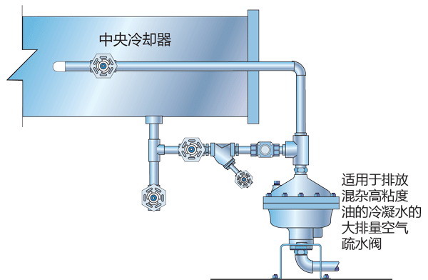
Figure 7 Condensate discharge when there are impurities in the compressed air system pipeline
For detailed information on how to establish and maintain steam balance, please refer to "Steam Balance Creates Benefits, CE 2004 July 36-41."
Related to this, a review of all condensate in the plant was conducted. In the past, the solution to correct the source of wasted condensate did not seem so economical, but now, as energy costs continue to rise, the scale of this part of the loss is expanding; Every time energy prices increase, specifically referring to fuel oil equivalent (FOES), from the perspective of return on investment, the need to re-evaluate and tap each potential condensate collection point and install a condensate recovery system is again on the agenda.
Capital or budget?
The embarrassment commonly encountered by factories now is: the energy saving team has explored opportunities for energy saving, but lacks sufficient financial support; occasionally when funds are issued, they often go to the maintenance budget-there are other restrictions that eventually lead to actual implementation The funds are scarce.
A popular practice is to set up special funds for energy-saving retrofits in stages, and at the same time, strictly abide by the system of applying for future budgets only after reaching the expected benefits at a certain stage. This "staged threshold" setting can provide necessary financial support for the improvement of the entire plant system.
When the company's financial department reviews and evaluates energy-saving renovation projects and other projects, it can take the return on investment as the standard and select the project with the highest return on investment to pass the review. Certain steam system improvement projects can meet capital investment requirements and improve plant efficiency on the basis of reducing operating costs. Highly concerned business/energy conservation consulting companies or individuals with "Certified Energy Conservation Manager" (C.E.M) certificates can assist clients in analyzing the feasibility of specific energy conservation projects from a financial perspective.
Thoughts
A well-run factory will include all input resources into its operating costs. Some resource costs, such as labor costs, will not change greatly over time; and some resource costs, such as energy or steam, are It is closely linked to the cost of FOE (fuel oil equivalent). For most factories, it is easier and faster to focus on improving the quality of the steam system to make profits for the company than to spend time looking for more economical fuel or energy.

